Upward Continuous Oxygen-free Copper Casting Machine
Brief Introduction
This upward continuous casting system is used to produce bright and long oxygen-free copper rod. The system is capable of producing directly from cathode copper to bright and long oxygen-free copper rod , copper tube, flat copper bar and other special shaped copper product.
As compared with the black copper rod produced by traditional mangler from copper ingot, the rod produced by this new upward continuous casting technology has its advantage of better quality, low production cost, low investment and no pollution in production.
Detailed Information
Main Composed Parts
1. Induction furnace
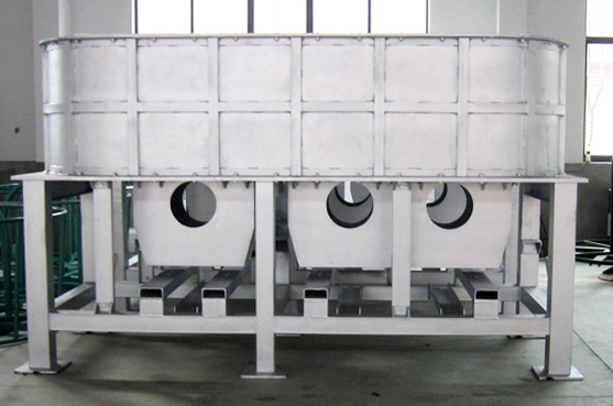
The induction furnace is consist of furnace body, furnace frame and inductor. The outside of the furnace body is steel structure and the inside is consist of fire-clay brick and quartz sand. The function of the furnace frame is supporting the whole furnace. The furnace is fixed on the base by the foot screw. The inductor is made up of coil, water jacket, iron core and copper-ring. There are coils with water-jacket at the high voltage side. The voltage is adjustable step by step from 90V to 420V.There are short-circuit copper rings at the low-voltage side. After set up an electric circuit, it can emerge big current flow in the copper ring with the electromagnetic induction. The big current flow can melt the copper ring and electrolytic copper putted into the furnace.The water jacket and coil is cooled by the water.The cooling water is cycling and supplied by the cooling water system.

2. Continuous casting machine,guiding rolls and limiting device
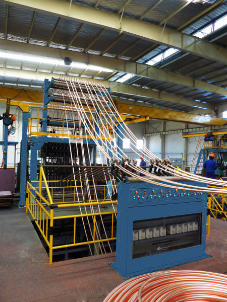
The continuous casting machine is the main part of the system. It consists of drawing mechanism, following mechanism of liquid level and crystallizer. The drawing mechanism is made up of A.C. servo motor, two groups of drawing rollers and so on..It can produce 0-1000 times interval rotation per minute and draw up the copper rod continuous by the drawing rollers. The following mechanism of liquid level guarantee that the deep of the crystallizer inserting into the copper liquid is relative stable.The crystallizer can cool the copper liquid into copper rod by heat exchange. Every crystallizer can be changed and controlled alone.
The frame of guide rolls is installed above the continuous casting machine. It is consist of platform, support, vertical guide pulley and cylinder. It can lead the copper rod to the every double-head wind machine without disturbance.
There is a speed control device between casting machine and take-up machine to synchronize casting speed and take-up speed with frequency changers.

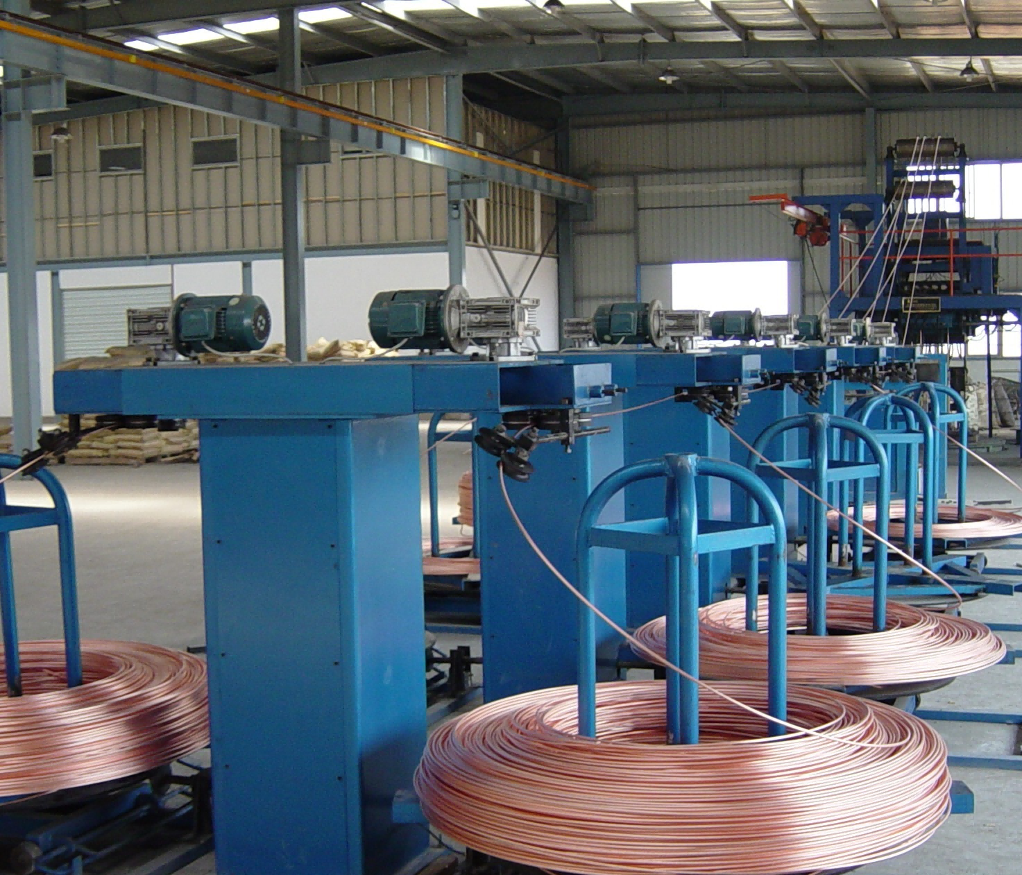
3.Double-head take-up machine

4. Cooling water system
The cooling water system is a cycling system. It can supply 0.2-0.4Mpa cooling water for freezer, water jacket, coil. It is consist of 150M3 water pool, water pump, tube and cooling water tower. The temperature of water supplied to the system is 20℃-30 and the quantity of water ℃ flow is 50 M3/H7,Electrical system .The electrical system is consist of electrical power and control system. The electrical power system supply the energy to every inductor through the power cabinets. The control system control the combined furnace, main machine, double-head wind machine and cooling water system pledging them to work in order. The control system of combined furnace is consist of melting furnace system and holding furnace system. The melting furnace operation cabinet and holding furnace operation cabinet are installed near the system.
5. Electric control system
The main machine electrical control system is consist of drawing motor, elevator motor and their electrical control system. The drawing motor is disposed control system alone. Every double-head wind machine is controlled alone. A taking-up controlling board is fixed in the frame of double-head wind machine. Its control knob is fixed on the surface of the frame. The cooling water electrical system is an control box hung on the wall of water pump room. It can control two water pumps.
Final Copper Rod Technical Standard
| 1 | Density | 8.9kg/dm^3 |
| 2 | Tensile strength | >170N/mm² |
| 3 | Elongation | >35% |
| 4 | Electrical conductivity | no less than 100%IACS (2mm dia soft wire) |
| 5 | Oxygen content | ≤10ppm |
Technical Parameters
| No. | Models | No of Rods | Specifications (mm) | Induction Furnace Model | Annual Output (T) | Motor | Take-up Weight(kg) | Loading Capacity | Electricity consumption( kWh/t ) |
| 1 | F4-Q2-8/20 | 4 | 8 - 20 | Double core | 2000 | Servo motor | ≤3000kg | 330 | ≤350 |
| 2 | F6-Q3-8/20 | 6 | 8 - 20 | Double core | 3000 | Servo motor | ≤3000kg | 330 | ≤350 |
| 3 | F8-Q4-8/20 | 8 | 8 - 20 | Three conbined core | 4000 | Servo motor | ≤3000kg | 480 | ≤340 |
| 4 | F10-Q5-8/20 | 10 | 8 - 20 | Three conbined core | 5000 | Servo motor | ≤3000kg | 480 | ≤340 |
| 5 | F12-Q6-8/20 | 12 | 8 - 20 | Three conbined core | 6000 | Servo motor | ≤3000kg | 480 | ≤340 |
| 6 | F16-Q8-8/20 | 16 | 8 - 20 | Three conbined core | 8000 | Servo motor | ≤3000kg | 750 | ≤330 |
| 7 | F20-Q10-8/20 | 20 | 8 - 20 | Three conbined core | 10000 | Servo motor | ≤3000kg | 950 | ≤330 |
| 8 | F24-Q12-8/20 | 24 | 8 - 20 | Three conbined core | 12000 | Servo motor | ≤3000kg | 1000 | ≤320 |
| 9 | F30-Q15-8/20 | 30 | 8 - 20 | Three conbined core | 15000 | Servo motor | ≤3000kg | 1100 | ≤320 |
Layout


